|
Moteur de recherche de fiches techniques de composants électroniques |
|
|
Moteur de recherche de fiches techniques de composants électroniques |
|
EMC2104 Fiches technique(PDF) 86 Page - SMSC Corporation |
|
|
|||||||||||||||||||||||||||||
EMC2104 Fiches technique(HTML) 86 Page - SMSC Corporation |
|
|
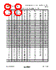
86 / 101 page  Dual RPM-Based PWM Fan Controller with Hardware Thermal Shutdown Datasheet Revision 1.74 (05-08-08) 86 SMSC EMC2104 DATASHEET Appendix A Thermistors The EMC2104 can monitor thermistor inputs on the TRIP_SET / VIN4 as well as supporting a thermistor option on the all of the external diode pins pairs (DP1 / VREF_T1 and DN1 / VIN1,etc.). The Thermistors can be connected as shown in Figure A.1. Figure A.1 is representative of one of the thermistor channels and will apply to DP1 / VREF_T1 and DN1 / VIN1, DP2 / VREF_T2 and DN2 / VIN2. The top side resistor is internally integrated in the case of the TRIP_SET / VIN4 channel and the VREF voltage will not be brought out externally. The Thermistor should be connected in the same way as RSET. The relationship between voltage and temperature is roughly linear. the measured voltage by the EMC2104 will be inversely proportional to temperature . Linearization methods can only accurately capture the temperature over a limited window of temperatures. For a 10k Ohm type 3370 Thermistor and a 1.2k ohm ±1% setting resistor, the output response corresponding to a thermistor is tabulated in Table A.1. If the INV_VINx bit is set then the results of the circuit (configured as shown in Figure A.1) is shown in Table A.2. The EMC2104 does not perform any numerical calculations on the thermistor value if a thermistor is monitored on TRIP_SET / VIN4 pin. If the External Diode 1, External Diode 2, or External Diode 3 channels are configured to measure a thermistor, it must be configured as shown in Figure A.1. When measuring a thermistor input with Fan Control Look Up Table, care must be taken that the temperature thresholds are entered as a unsigned voltage number that corresponds to the desired thermal threshold. Also note that the LUT assumes that the VIN1 and TRIP_SET / VIN4 voltage inputs are directly proportional to temperature. Figure A.1 “Low Side” Thermistor Connection 10K 1% Thermistor DP3 / DN4 / VREF_T3 DN3 / DP4 / VIN3 1.2K 1% 0.1uF EMC2104/5/6 ADC Buffer Reference Voltage |
|
Lien URL |
| ALLDATASHEET vous a-t-il été utile ? [ DONATE ] |
À propos de Alldatasheet | Publicité | Contactez-nous | Politique de confidentialité | Lien vers la fiche technique | Echange de liens | Fabricants All Rights Reserved©Alldatasheet.com |
| Russian : Alldatasheetru.com | Korean : Alldatasheet.co.kr | Spanish : Alldatasheet.es | French : Alldatasheet.fr | Italian : Alldatasheetit.com Portuguese : Alldatasheetpt.com | Polish : Alldatasheet.pl | Vietnamese : Alldatasheet.vn Indian : Alldatasheet.in | Mexican : Alldatasheet.com.mx | British : Alldatasheet.co.uk | New Zealand : Alldatasheet.co.nz |
|
Family Site : ic2ic.com |
icmetro.com |
 French ▼
 English
 Chinese
 German
 Japanese
 Russian
 Korean
 Spanish
 French
 Italian
 Portuguese
 Polish
 Vietnamese
 Indian
 Mexican
 British
 New Zealand