|
Moteur de recherche de fiches techniques de composants électroniques |
|
|
Moteur de recherche de fiches techniques de composants électroniques |
|
EMC2104 Fiches technique(PDF) 60 Page - SMSC Corporation |
|
|
|||||||||||||||||||||||||||||
EMC2104 Fiches technique(HTML) 60 Page - SMSC Corporation |
|
|
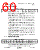
60 / 101 page  Dual RPM-Based PWM Fan Controller with Hardware Thermal Shutdown Datasheet Revision 1.74 (05-08-08) 60 SMSC EMC2104 DATASHEET 6.14 Fan Status Register The Fan Status Register contains the status bits associated with each fan driver. This register is cleared when read if the error condition has been removed. Bit 7 - WATCH - This bit is asserted ‘1’ if the host has not programmed the fan driver(s) within four (4) seconds after power up. Bit 6 - DRIVE_FAIL2 - Indicates that the RPM based Fan Speed Control Algorithm cannot drive Fan 2 to the desired target setting at maximum drive. This bit can be masked from asserting the ALERT# pin. ‘0’ - The RPM based Fan Speed Control Algorithm can drive Fan 2 to the desired target setting. ‘1’ - The RPM based Fan Speed Control Algorithm cannot drive Fan 2 to the desired target setting at maximum drive. Bit 6 - DRIVE_FAIL1 - Indicates that the RPM based Fan Speed Control Algorithm cannot drive Fan 1 to the desired target setting at maximum drive. This bit can be masked from asserting the ALERT# pin. ‘0’ - The RPM based Fan Speed Control Algorithm can drive Fan 1 to the desired target setting. ‘1’ - The RPM based Fan Speed Control Algorithm cannot drive Fan 1 to the desired target setting at maximum drive. Bit 3 - FAN_SPIN 2- This bit is asserted ‘1’ if the Spin up Routine for Fan 2 cannot detect a valid tachometer reading within its maximum time window. This bit can be masked from asserting the ALERT# pin. Bit 2 - FAN_STALL 2 - This bit is asserted ‘1’ if the tachometer measurement on Fan 2 detects a stalled fan. This bit can be masked from asserting the ALERT# pin. Bit 1- FAN_SPIN1- This bit is asserted ‘1’ if the Spin up Routine for Fan 1 cannot detect a valid tachometer reading within its maximum time window. This bit can be masked from asserting the ALERT# pin. Bit 0 - FAN_STALL1 - This bit is asserted ‘1’ if the tachometer measurement on Fan 1 detects a stalled fan. This bit can be masked from asserting the ALERT# pin. 6.15 Interrupt Enable Register The Interrupt Enable Register controls the masking for each temperature channel. When a channel is masked, it will not cause the ALERT# pin to be asserted when an error condition is detected. Bit 5 - VOLT4_INT_EN - Allows the Voltage Input 4 channel to assert the ALERT# pin. Table 6.19 Fan Status Register ADDR R/W REGISTER B7 B6 B5 B4 B3 B2 B1 B0 DEFAULT 27h R-C Fan Status Register WATCH DRIVE _FAIL2 DRIVE _FAIL1 - FAN_ SPIN2 FAN_ STALL2 FAN_ SPIN1 FAN_ STALL1 00h Table 6.20 Interrupt Enable Register ADDR R/W REGISTER B7 B6 B5 B4 B3 B2 B1 B0 DEFAULT 28 R/W Interrupt Enable -- VOLT4_I NT_EN EXT4_I NT_EN EXT3_I NT_EN EXT2_I NT_EN EXT1_I NT_EN INT_IN T_EN 00h |
|
Lien URL |
| ALLDATASHEET vous a-t-il été utile ? [ DONATE ] |
À propos de Alldatasheet | Publicité | Contactez-nous | Politique de confidentialité | Lien vers la fiche technique | Echange de liens | Fabricants All Rights Reserved©Alldatasheet.com |
| Russian : Alldatasheetru.com | Korean : Alldatasheet.co.kr | Spanish : Alldatasheet.es | French : Alldatasheet.fr | Italian : Alldatasheetit.com Portuguese : Alldatasheetpt.com | Polish : Alldatasheet.pl | Vietnamese : Alldatasheet.vn Indian : Alldatasheet.in | Mexican : Alldatasheet.com.mx | British : Alldatasheet.co.uk | New Zealand : Alldatasheet.co.nz |
|
Family Site : ic2ic.com |
icmetro.com |
 French ▼
 English
 Chinese
 German
 Japanese
 Russian
 Korean
 Spanish
 French
 Italian
 Portuguese
 Polish
 Vietnamese
 Indian
 Mexican
 British
 New Zealand