|
Moteur de recherche de fiches techniques de composants électroniques |
|
|
Moteur de recherche de fiches techniques de composants électroniques |
|
L99MH98 Fiches technique(PDF) 5 Page - STMicroelectronics |
|
|
|||||||||||||||||||||||||||||
L99MH98 Fiches technique(HTML) 5 Page - STMicroelectronics |
|
|
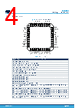
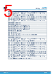
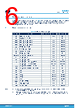
5 / 147 page  # Name Function 19 GH7 GH7 gate high-side 7: analog output pin to turn on/off high-side MOSFET 7. Connect to the gate of the high side 20 SH7 SH7 source high-side 7: connection to source of high-side MOSFET 7 21 GL7 GL7 gate low-side 7: analog output pin to turn on/off low-side MOSFET 7. Connect to the gate of the low side 22 GL8 GL8 gate low-side 8: analog output pin to turn on/off low-side MOSFET 8. Connect to the gate of the low side 23 SH8 SH8 source high-side 8: connection to source of high-side MOSFET 8 24 GH8 GH8 gate high-side 8: analog output pin to turn on/off high-side MOSFET 8. Connect to the gate of the high side 25 DIODE4 External diode control 4 26 DIODE3 External diode control 3 27 CP1P CP1P:positive connection to charge pump capacitor 1 28 CP1N CP1N: negative connection to charge pump capacitor 1 29 CP2N CP2N: negative connection to charge pump capacitor 2 30 CP2P CP2P: Positive connection to charge pump capacitor 2 31 CPOUT CPOUT: Charge pump output 32 VDH VDH input pin 33 GND GND Ground connection 34 SL SL source low-side: common connection to the source of the low-side MOSFETs 35 DIODE2 External diode control 2 36 DIODE1 External diode control 1 37 GH4 GH4 gate high-side 4: analog output pin to turn on/off high-side MOSFET 4. Connect to the gate of the high side 38 SH4 SH4 source high-side 4: connection to source of high-side MOSFET 4 39 GL4 GL4 gate low-side 4: analog output pin to turn on/off low-side MOSFET 4. Connect to the gate of the low side 40 GL3 GL3 gate low-side 3: analog output pin to turn on/off low-side MOSFET 3. Connect to the gate of the low side 41 SH3 SH3 source high-side 3: connection to source of high-side MOSFET 3 42 GH3 GH3 gate high-side 3: analog output pin to turn on/off high-side MOSFET 3. Connect to the gate of the high side 43 GH2 GH2 gate high-side 2: analog output pin to turn on/off high-side MOSFET 2. Connect to the gate of the high side 44 SH2 SH2 source high-side 2: connection to source of high-side MOSFET 2 45 GL2 GL2 gate low-side 2:analog output pin to turn on/off low-side MOSFET 2. Connect to the gate of the low side 46 GL1 GL1 gate low-side 1: analog output pin to turn on/off low-side MOSFET 1. Connect to the gate of the low side 47 SH1 SH1 source high-side 1: connection to source of high-side MOSFET 1 48 GH1 GH1 gate high-side 1: analog output pin to turn on/off high-side MOSFET 1. Connect to the gate of the high side - E.P. Exposed pad connected to ground on the application board L99MH98 Block diagram and pin description DS14611 - Rev 3 page 5/147 |
|
Lien URL |
| ALLDATASHEET vous a-t-il été utile ? [ DONATE ] |
À propos de Alldatasheet | Publicité | Contactez-nous | Politique de confidentialité | Lien vers la fiche technique | Echange de liens | Fabricants All Rights Reserved©Alldatasheet.com |
| Russian : Alldatasheetru.com | Korean : Alldatasheet.co.kr | Spanish : Alldatasheet.es | French : Alldatasheet.fr | Italian : Alldatasheetit.com Portuguese : Alldatasheetpt.com | Polish : Alldatasheet.pl | Vietnamese : Alldatasheet.vn Indian : Alldatasheet.in | Mexican : Alldatasheet.com.mx | British : Alldatasheet.co.uk | New Zealand : Alldatasheet.co.nz |
|
Family Site : ic2ic.com |
icmetro.com |
 French ▼
 English
 Chinese
 German
 Japanese
 Russian
 Korean
 Spanish
 French
 Italian
 Portuguese
 Polish
 Vietnamese
 Indian
 Mexican
 British
 New Zealand