 |
Moteur de recherche de fiches techniques de composants électroniques |
|
|
Moteur de recherche de fiches techniques de composants électroniques |
|
The question interval is too short.
Please try again in a few seconds.

Hello, Please ask a question about ST10F269Z1Q6 Datasheet
# Example questions:
➢ The datasheet mentions both 'wr' and 'wrl' modes for the ~~wr/wrl~~ pin. explain the difference between these two modes and how they are configured.
➢ What is the purpose of the ~~ea~~ pin, and how does its logic level (high or low) affect the microcontroller's boot-up behavior?
➢ What are the primary functions of port 4, and how can it be used in an external bus configuration?
| Part No. | ST10F269Z1Q6 |
| Manufacturer | STMICROELECTRONICS |
| Size | 3Mb |
| Pages | 184 pages |
| Description | 16-BIT MCU WITH MAC UNIT, 128K to 256K BYTE FLASH MEMORY AND 12K BYTE RAM |


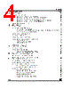


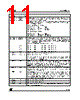

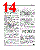

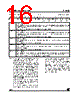
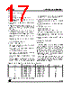
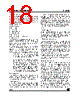
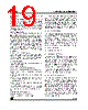
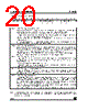
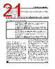
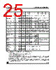

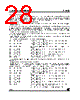
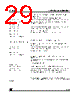


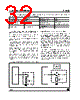
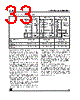

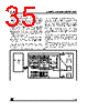
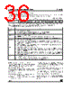
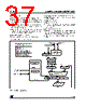


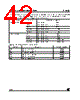
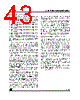
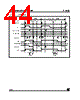

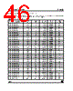
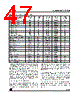

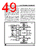
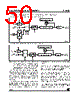
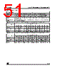
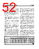
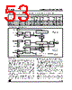
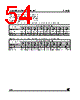

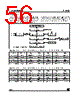
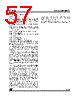


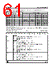
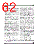
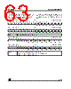
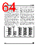
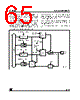

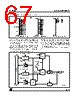
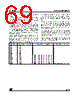
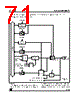

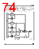
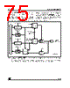
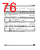
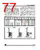
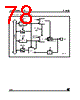
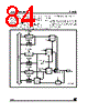
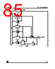


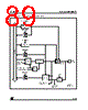
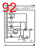

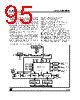
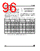
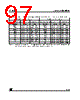
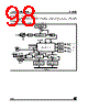





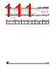
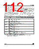

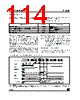
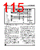







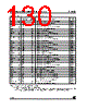
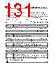
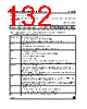


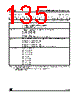





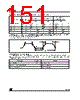
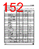

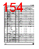
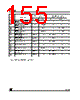





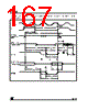
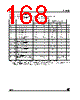

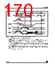
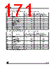


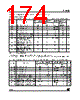
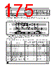
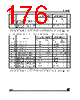

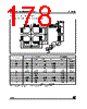



## Summary of the Provided Text (ST10F269 Pinout & Descriptions)
This document details the pinout and functionality of the ST10F269 microcontroller. Here's a breakdown of the key information:
️· Comprehensive Pin Descriptions: It lists each pin of the ST10F269, including its symbol, pin number, input/output type (I, O, or I/O), and a detailed description of its function.
️· Port-Based Organization: Pins are grouped and described by their corresponding ports (P2, P3, P4, etc.).
️· Multiple Functions: Many pins have multiple functions or alternate uses, which are clearly explained. This includes:
- General Purpose I/O (GPIO): Basic input/output capabilities.
- External Memory Interface: Pins dedicated to interfacing with external memory (address lines, read/write strobes, etc.).
- Serial Communication: Pins for communication protocols like UART (ASC0), SPI (SSC), and CAN.
- Timers/Counters: Pins connected to the microcontroller's timer/counter modules.
- Interrupts: External interrupt inputs.
️· Configurable Options: Several pin functions are configurable, allowing the user to customize the microcontroller’s behavior. This includes:
- Input threshold levels (TTL or special)
- Open-drain vs. push-pull output configuration
- Ready signal active level
- External memory access modes (WR/WRL)
️· External Bus Support: The pinout clearly indicates pins that support external memory interfacing for expanded program and data storage.
️· Detailed Explanations: Descriptions go into sufficient detail to understand each pin's purpose and how it interacts with the system.
In essence, this document is a technical reference guide for anyone designing a system using the ST10F269 microcontroller, providing all the necessary information to correctly connect and configure the microcontroller's pins.
## Summary of the Provided Text (ST10F269 Pinout & Descriptions)
This document details the pinout and functionality of the ST10F269 microcontroller. Here's a breakdown of the key information:
️· Comprehensive Pin Descriptions: It lists each pin of the ST10F269, including its symbol, pin number, input/output type (I, O, or I/O), and a detailed description of its function.
️· Port-Based Organization: Pins are grouped and described by their corresponding ports (P2, P3, P4, etc.).
️· Multiple Functions: Many pins have multiple functions or alternate uses, which are clearly explained. This includes:
- General Purpose I/O (GPIO): Basic input/output capabilities.
- External Memory Interface: Pins dedicated to interfacing with external memory (address lines, read/write strobes, etc.).
- Serial Communication: Pins for communication protocols like UART (ASC0), SPI (SSC), and CAN.
- Timers/Counters: Pins connected to the microcontroller's timer/counter modules.
- Interrupts: External interrupt inputs.
️· Configurable Options: Several pin functions are configurable, allowing the user to customize the microcontroller’s behavior. This includes:
- Input threshold levels (TTL or special)
- Open-drain vs. push-pull output configuration
- Ready signal active level
- External memory access modes (WR/WRL)
️· External Bus Support: The pinout clearly indicates pins that support external memory interfacing for expanded program and data storage.
️· Detailed Explanations: Descriptions go into sufficient detail to understand each pin's purpose and how it interacts with the system.
In essence, this document is a technical reference guide for anyone designing a system using the ST10F269 microcontroller, providing all the necessary information to correctly connect and configure the microcontroller's pins.
| Part No. | ST10F269Z1Q6 |
| Manufacturer | STMICROELECTRONICS |
| Size | 3Mb |
| Pages | 184 pages |
| Description | 16-BIT MCU WITH MAC UNIT, 128K to 256K BYTE FLASH MEMORY AND 12K BYTE RAM |
| ALLDATASHEET vous a-t-il été utile ? [ DONATE ] |
À propos de Alldatasheet | Publicité | Contactez-nous | Politique de confidentialité | Lien vers la fiche technique | Echange de liens | Fabricants All Rights Reserved©Alldatasheet.com |
| Russian : Alldatasheetru.com | Korean : Alldatasheet.co.kr | Spanish : Alldatasheet.es | French : Alldatasheet.fr | Italian : Alldatasheetit.com Portuguese : Alldatasheetpt.com | Polish : Alldatasheet.pl | Vietnamese : Alldatasheet.vn Indian : Alldatasheet.in | Mexican : Alldatasheet.com.mx | British : Alldatasheet.co.uk | New Zealand : Alldatasheet.co.nz |
|
Family Site : ic2ic.com |
icmetro.com |
 French ▼
  English
 Chinese
 German
 Japanese
 Russian
 Korean
 Spanish
 Italian
 Portuguese
 Polish
 Vietnamese
 Indian
 Mexican
 British
 New Zealand