|
Moteur de recherche de fiches techniques de composants électroniques |
|
|
Moteur de recherche de fiches techniques de composants électroniques |
|
ADIS16240ABCZ Fiches technique(PDF) 13 Page - Analog Devices |
|
|
|||||||||||||||||||||||||||||
ADIS16240ABCZ Fiches technique(HTML) 13 Page - Analog Devices |
|
|
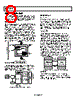
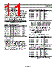
13 / 16 page  ADIS16240 Rev. 0 | Page 13 of 16 8192 SAMPLES EVENT 1 EVENT NE NL NL = 2T 1024 NE = 8 × 2T EVENT 2 Figure 20. Event Storage in Buffer Memory For example, if CAPT_CTRL[2:0] = 100, then T = 4, which organizes the buffer memory into 128 events of 64 samples each. Event Organization Each event contains a header, pretrigger data, and posttrigger data, as shown in Figure 21. The event header provides information about the conditions that occur when the capture takes place. CAPT_CTRL[7:4] sets the number of pretrigger samples in each event. If NPRE is negative, there is no pretrigger data and the first sample after the trigger follows the header. 6 16 − = L PRE N N XYZPEAK_OUT TIME DATE TEMP_OUT SUPPLY_OUT AUX_ADC 0 0 0 0 0 0 Z–26 Z–25 Z–1 Z0 Z1 Y–1 Y0 Y1 X–1 X0 X1 Z223 Y223 X223 Y–26 Y–25 X–26 X–25 0 0 0 0 0 0 0 0 255 0 1 2 3 4 5 6 7 31 32 33 POSTTRIGGER DATA PRETRIGGER DATA EVENT HEADER BUFFER 2 BUFFER 1 Figure 21. Default Event Organization Reading Event Data The CAPT_BUF1, CAPT_BUF2, and CAPT_PNTR registers manage user access to data in the capture buffer (see Table 18, Table 19, and Table 20). The address pointer, CAPT_PNTR, determines which capture memory location loads into the capture buffer registers. It increments automatically with every CAPT_ BUF2 read. The most efficient method for reading the entire buffer memory space is to alternate between the CAPT_BUF1 (DIN = 0x9600) and CAPT_BUF2 (DIN = 0x9800) read com- mands. When alternating the read sequences in this manner, the CAP_PNTR increments automatically and optimizes SPI processing resources. Writing to the CAPT_PNTR register pro- vides access to individual locations in the capture. For example, writing 0x0138 (DIN = 0xC038, DIN = 0xC101) to the CAPT_ PNTR register causes the 311th sample in each buffer memory to load into the CAP_BUF1 and CAPT_BUF2 locations (see Figure 22). Table 18. CAPT_BUF1 Register Bit Descriptions1 Bit Description Format [15:8] Y-axis acceleration Twos complement, 205.7 mg/LSB [7:0] X-axis acceleration 1 The CAPT_BUF1 register is located at Address 0x17[15:8] and Address 0x16[7:0]. Table 19. CAPT_BUF2 Register Bit Descriptions1 Bit Description Format [15:8] Unused Twos complement, 205.7 mg/LSB [7:0] Z-axis acceleration 1 The CAPT_BUF2 register is located at Address 0x19[15:8] and Address 0x18[7:0]. Table 20. CAPT_PNTR Register Bit Descriptions1 Bit Description [15:13] Unused [7:0] Buffer address that loads into CAPT_BUF1, CAPT_BUF2 1 The CAPT_PNTR register is located at Address 0x41[15:8] and Address 0x40[7:0]. CAPT_PNTR CAPT_BUF2 USER ACCESIBLE INTERNAL MEMORY STRUCTURE CAPT_BUF1 BUFFER 2 BUFFER 1 Figure 22. Capture Buffer Data Flow Diagram The EVNT_CNTR register (see Table 21) provides a running count for the number of triggers (internal and external) that occur after a buffer clear and/or reset. If this number is greater than the number of events, this indicates that the device has experienced trigger events that it could not capture because its capture buffer is full. The EVNT_CNTR returns to 0x0000 after a buffer clear (GLOB_CMD[6] = 1 by DIN = 0xCA40), or a factory reset (GLOB_CMD[1] = 1 by DIN = 0xCA02). After a power cycle or software reset command, the EVNT_CNTR contains the number of events stored in the buffer memory. Table 21. EVNT_CNTR Register Bit Descriptions1 Bit Description [15:0] Binary event counter 1 The EVNT_CNTR register is located at Address 0x1D[15:8] and Address 0x1C[7:0]. |
|
|
Lien URL |
| ALLDATASHEET vous a-t-il été utile ? [ DONATE ] |
À propos de Alldatasheet | Publicité | Contactez-nous | Politique de confidentialité | Lien vers la fiche technique | Echange de liens | Fabricants All Rights Reserved©Alldatasheet.com |
| Russian : Alldatasheetru.com | Korean : Alldatasheet.co.kr | Spanish : Alldatasheet.es | French : Alldatasheet.fr | Italian : Alldatasheetit.com Portuguese : Alldatasheetpt.com | Polish : Alldatasheet.pl | Vietnamese : Alldatasheet.vn Indian : Alldatasheet.in | Mexican : Alldatasheet.com.mx | British : Alldatasheet.co.uk | New Zealand : Alldatasheet.co.nz |
|
Family Site : ic2ic.com |
icmetro.com |
 French ▼
 English
 Chinese
 German
 Japanese
 Russian
 Korean
 Spanish
 French
 Italian
 Portuguese
 Polish
 Vietnamese
 Indian
 Mexican
 British
 New Zealand