|
Moteur de recherche de fiches techniques de composants électroniques |
|
|
Moteur de recherche de fiches techniques de composants électroniques |
|
ADIS16240ABCZ Fiches technique(PDF) 12 Page - Analog Devices |
|
|
|||||||||||||||||||||||||||||
ADIS16240ABCZ Fiches technique(HTML) 12 Page - Analog Devices |
|
|
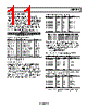
12 / 16 page  ADIS16240 Rev. 0 | Page 12 of 16 EVENT RECORDER The ADIS16240 provides a 3 × 8192 (8-bit) buffer memory for reading transient acceleration data on all three axes (x, y, and z). There are a number of user controls for tailoring the event recorder for optimal system-level operation. Alarm 1 and Alarm 2 provide internal and external trigger options for starting a data capture sequence. Internal Trigger Setup Select the trigger data source for Alarm 1 and Alarm 2 using ALM_CTRL[15:8] (see Table 12). The ALM_MAG1 and ALM_ MAG2 registers contain threshold magnitude and direction settings for Alarm 1 and Alarm 2, respectively. The format for the data bits in these registers matches the trigger data source, which is set using ALM_CTRL[15:8]. For example, if ALM_ CTRL[15:12] equals 0010, then the format matches that of XACCL_OUT: 10-bit, twos complement, with 1 LSB = 51.4 mg of acceleration. Table 12. ALM_CTRL Register Bit Descriptions1 Bit Description (Default = 0x0000) [15:12] Alarm 2 source selection 0000 = disabled 0001 = power supply voltage (SUPPLY_OUT) 0010 = x acceleration (XACCL_OUT) 0011 = y acceleration (YACCL_OUT) 0100 = z acceleration (ZACCL_OUT) 0101 = auxiliary ADC voltage (AUX_ADC) 0110 = temperature (TEMP_OUT) 0111 = XYZ peak acceleration (XYZPEAK_OUT) 1000 = external trigger [11:8] Alarm 1 source selection (same as Alarm 2) [7:6] Unused 5 Alarm 2 capture trigger: 1 = enabled, 0 = disabled 4 Alarm 1 capture trigger: 1 = enabled, 0 = disabled 3 Unused 2 Alarm indicator enable: 1 = enabled, 0 = disabled 1 Alarm indicator polarity: 1 = positive, 0 = negative 0 Alarm indicator pin: 1 = DIO2, 0 = DIO1 1 The ALM_CTRL register is located at Address 0x3D[15:8] and Address 0x3C[7:0]. Table 13. ALM_MAG1, ALM_MAG2 Register Bit Descriptions1 Bit Description (Default = 0x9000) 15 Threshold direction 1 = active for output greater than alarm magnitude 0 = inactive for output less than alarm magnitude 14 Unused [13:0] Trigger threshold; bit format matches that of the register selected by ALM_CTRL[15:8] but is unsigned. 1 The ALM_MAG1 register is located at Address 0x39[15:8] and Address 0x38[7:0]. The ALM_MAG2 register is located at Address 0x3B[15:8] and Address 0x3A[7:0]. Table 14. Internal Trigger Setup Example DIN Description 0xBD44 Set Alarm 1 and Alarm 2 to ZACCL_OUT 0xB980, 0xB832 Set Alarm 1 to trigger on a measured acceleration that has a magnitude of >2.57 g 0xBB00, 0xBA0A Set Alarm 2 to trigger on a measured acceleration that has a magnitude of <0.5 g 0xBC37 Activate Alarm 1 and Alarm 2 to trigger capture events, and configure DIO2 as a positive alarm indicator output. External Trigger Setup ALM_CTRL[15:8] and XTRIG_CTRL (see Table 15) provide all of the settings needed to govern the use of the comparator pins (CMP1, CMP2) as external trigger inputs. Table 15. XTRIG_CTRL Register Bit Descriptions1 Bit Description (Default = 0x0000) [15:8] Unused 7 External Trigger 1 direction: 0 = <, 1 = > 6 External Trigger 2 direction: 0 = <, 1 = > 5 External Trigger 1 enable: 1 = enabled, 0 = disabled 4 External Trigger 2 enable: 1 = enabled, 0 = disabled [3:0] External trigger-level setting (TL), binary format Note that trigger threshold = TL × supply/24 1 The XTRIG_CTRL register is located at Address 0x3F[15:8] and Address 0x3E[7:0]. Table 16. External Trigger Setup Example DIN Description 0xBD80 Set Alarm 2 to an external trigger (ALM_CTRL) 0xBE1C Activate and set CMP2 to trigger on signals that are greater than one-half of the supply voltage (XTRIG_CTRL) 0xBC20 Activate Alarm 2 to trigger data capture (ALM_CTRL) If the device is in standby mode, an external trigger on CMD1 or CMD2 awakens the device and initiates an event capture. The first sample is taken 0.2 ms + sample period (SMPL_PRD[7:0]) after the trigger edge. Buffer Memory Configuration CAPT_CTRL (see Table 17) manages the buffer memory for the event recorder using two programmable controls: event length and pretrigger length. Table 17. CAPT_CTRL Register Bit Descriptions1 Bit Description (Default = 0x0022) [15:8] Unused [7:4] Pretrigger length control factor (P), binary format 3 Unused [2:0] Event length control factor (T), binary format 1 The CAPT_CTRL register is located at Address 0x43[15:8] and Address 0x42[7:0]. The event length (NL) also determines the number of events (NE) that the buffer can store at one time. |
|
|
Lien URL |
| ALLDATASHEET vous a-t-il été utile ? [ DONATE ] |
À propos de Alldatasheet | Publicité | Contactez-nous | Politique de confidentialité | Lien vers la fiche technique | Echange de liens | Fabricants All Rights Reserved©Alldatasheet.com |
| Russian : Alldatasheetru.com | Korean : Alldatasheet.co.kr | Spanish : Alldatasheet.es | French : Alldatasheet.fr | Italian : Alldatasheetit.com Portuguese : Alldatasheetpt.com | Polish : Alldatasheet.pl | Vietnamese : Alldatasheet.vn Indian : Alldatasheet.in | Mexican : Alldatasheet.com.mx | British : Alldatasheet.co.uk | New Zealand : Alldatasheet.co.nz |
|
Family Site : ic2ic.com |
icmetro.com |
 French ▼
 English
 Chinese
 German
 Japanese
 Russian
 Korean
 Spanish
 French
 Italian
 Portuguese
 Polish
 Vietnamese
 Indian
 Mexican
 British
 New Zealand