|
Moteur de recherche de fiches techniques de composants électroniques |
|
|
Moteur de recherche de fiches techniques de composants électroniques |
|
E5CD-RX2ABM-001 Fiches technique(PDF) 47 Page - Omron Electronics LLC |
|
|
|||||||||||||||||||||||||||||
E5CD-RX2ABM-001 Fiches technique(HTML) 47 Page - Omron Electronics LLC |
|
|
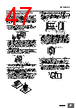
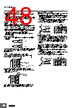
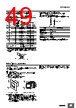
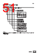
47 / 56 page  E5CD/E5ED 47 Drawing Out the Interior Body of the Digital Temperature Controller to Replace It You can use the Draw-out Jig to remove the interior body of the Digital Temperature Controller from the case to perform maintenance without removing the terminal leads. Use the Y92F-58 Draw-out Jig for the E5CD and the Y92F-59 Draw-out Jig for the E5ED. Check the specifications of the case and Digital Temperature Controller before removing the interior body from the case. (Drawout is not possible on the E5 @D-B.) 1. Draw out the interior body from the rear case. 1. Align the arms on the Draw-out Jig with the top of the front panel on the Digital Temperature Controller and position it vertically. (The Y92F-58 is shown in the figure.) 2. Align the hooks on the Draw-out Jig with the Draw-out Jig insertion holes on the Digital Temperature Controller and slowly insert the Draw-out Jig into the Draw-out Jig insertion holes laterally until it clicks into place. (If you attempt to draw out the interior body of the Digital Temperature Controller when only one hook is engaged, the Digital Temperature Controller may be damaged.) (The Y92F- 58 is shown in the figure.) 3. Pull out the Draw-out Jig together with the front panel. Do not pull with excessive force. Slowly pull out the Digital Temperature Controller laterally. (If you pull the interior body out at an angle, the Digital Temperature Controller may be damaged.) 4. After the interior body is free from the rear case, support the interior body with one hand and pull it out slowly in a horizontal direction. 2. Prepare the new interior body. 1. Place the Digital Temperature Controller flat on a table and slowly insert the Draw-out Jig into the Draw-out Jig insertion holes laterally until it clicks into place. (There is a hole at both the top and bottom.) (The E5CD is shown in the figure.) 2. Place the Digital Temperature Controller on a table facing upward. 3. Hold the rear case with your hand and slowly draw out the interior body in a vertical direction. If you draw out the interior body horizontally while holding the Digital Temperature Controller in your hand, the interior body will fall and may be damaged. 3. Insert the new interior body into the rear case. 1. When inserting the interior body back into the rear case, mount the sealing rubber in the position shown below, make sure the PCBs are parallel to each other, and press the interior body toward the rear case and into position, making sure that the sealing rubber does not move. 2. When you press the Digital Temperature Controller into position, press down on the rear case hooks so that the case hooks securely lock in place. (There are rear case hooks at both the top and bottom of the rear case.) If the Digital Temperature Controller is not correctly mounted into the rear case, the rear case may not be waterproof. When inserting the Digital Temperature Controller, do not allow the electronic components to touch the rear case. (The E5CD is shown in the figure.) Removing the draw-out jig when only one hook is caught in the draw-out jig insertion hole 1. Pull the Draw-out Jig slowly in the direction shown in the figure. (This step is the same even if the other hook is caught.) 2. Confirm that the Draw-out Jig is free of the Draw-out Jig insertion hole. 3. If the interior body separates from the rear case, slowly press the interior body into the rear case in a horizontal direction. (The E5CD is shown in the figure.) If you do not follow the procedures above, the Digital Temperature Controller may be damaged. Arm Front panel Rear case Draw-out Jig insertion holes (1) (1) Hook Align the arms with the front panel. Draw-out Jig insertion holes (2) (2) (3) (2) (3) (1) Top View Sealing rubber position Case hooks Rear case hooks PCBs Keep the PCBs parallel to each other and inset them into the rear case. (1) Rear case hooks (2) (2) (2) (1) (3) |
|
Lien URL |
| ALLDATASHEET vous a-t-il été utile ? [ DONATE ] |
À propos de Alldatasheet | Publicité | Contactez-nous | Politique de confidentialité | Lien vers la fiche technique | Echange de liens | Fabricants All Rights Reserved©Alldatasheet.com |
| Russian : Alldatasheetru.com | Korean : Alldatasheet.co.kr | Spanish : Alldatasheet.es | French : Alldatasheet.fr | Italian : Alldatasheetit.com Portuguese : Alldatasheetpt.com | Polish : Alldatasheet.pl | Vietnamese : Alldatasheet.vn Indian : Alldatasheet.in | Mexican : Alldatasheet.com.mx | British : Alldatasheet.co.uk | New Zealand : Alldatasheet.co.nz |
|
Family Site : ic2ic.com |
icmetro.com |
 French ▼
 English
 Chinese
 German
 Japanese
 Russian
 Korean
 Spanish
 French
 Italian
 Portuguese
 Polish
 Vietnamese
 Indian
 Mexican
 British
 New Zealand