|
Moteur de recherche de fiches techniques de composants électroniques |
|
|
Moteur de recherche de fiches techniques de composants électroniques |
|
L99MD02 Fiches technique(PDF) 28 Page - STMicroelectronics |
|
|
|||||||||||||||||||||||||||||
L99MD02 Fiches technique(HTML) 28 Page - STMicroelectronics |
|
|
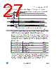
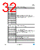
28 / 46 page  Functional description of the SPI L99MD02 28/46 Doc ID 16082 Rev 5 For read operations, the <communication error> bit in the <Global Status Byte> will be set, but the register to be read will still be transferred to the SDO pin. If the number of clock cycles is smaller than the frame width, the data at SDO will be truncated. If the number of clock cycles is larger than the frame width, the data at SDO will be filled with ‘0’ bits. Due to this safety functionality a daisy chaining of SPI is not possible. Instead, a parallel operation of the SPI bus by controlling the CSN signal of the connected ICs is recommended. Note: As the frame width is 24 bits, an initial read of <SPI-frame-ID> using a 16 bits communication will set the <communication Error bit> of the <Global Status Byte>. A subsequent correct length transaction is necessary to correct this bit. 6.3 Write operation OC0, OC1: operating code (00 for ‘write’ mode). The write operation starts with a command byte followed by 2 data bytes. For write cycles the <Global Status> register is followed by the previous content of the addressed register. The RAM memory area consists of 16 bit registers. All unused RAM addresses will be read as ‘0’. Failures are indicated by activating the corresponding bit of the <Global Status> register. Note: RAM address 00H is unused. An attempt to access this address is recognized as a communication line error (‘Data-in stuck to GND’) and all internal registers will be cleared (software reset). 6.4 Read operation OC0, OC1: operating code (01 for ‘read’ mode). The read operation starts with a command byte followed by 2 data bytes. The content of the data bytes is ‘don’t care’. The content of the addressed register is shifted out at SDO within the same frame (‘inframe response’). The returned data byte represents the content of the register to be read. Failures are indicated by activating the corresponding bit of the <Global Status> register. 6.5 Read and clear status operation OC0, OC1: operating code (10 for ‘read and clear status’ mode). The ‘Read and Clear Status’ operation starts with a command byte followed by 2 data bytes. The content of the data bytes is ‘don’t care’. The content of the addressed status register is transferred to SDO within the same frame (‘in-frame response’) and is subsequently cleared. A ‘Read and Clear Status’ operation with address 3FH clears all Status registers simultaneously. |
|
Lien URL |
| ALLDATASHEET vous a-t-il été utile ? [ DONATE ] |
À propos de Alldatasheet | Publicité | Contactez-nous | Politique de confidentialité | Lien vers la fiche technique | Echange de liens | Fabricants All Rights Reserved©Alldatasheet.com |
| Russian : Alldatasheetru.com | Korean : Alldatasheet.co.kr | Spanish : Alldatasheet.es | French : Alldatasheet.fr | Italian : Alldatasheetit.com Portuguese : Alldatasheetpt.com | Polish : Alldatasheet.pl | Vietnamese : Alldatasheet.vn Indian : Alldatasheet.in | Mexican : Alldatasheet.com.mx | British : Alldatasheet.co.uk | New Zealand : Alldatasheet.co.nz |
|
Family Site : ic2ic.com |
icmetro.com |
 French ▼
 English
 Chinese
 German
 Japanese
 Russian
 Korean
 Spanish
 French
 Italian
 Portuguese
 Polish
 Vietnamese
 Indian
 Mexican
 British
 New Zealand