|
Moteur de recherche de fiches techniques de composants électroniques |
|
|
Moteur de recherche de fiches techniques de composants électroniques |
|
AN1042 Fiches technique(PDF) 3 Page - STMicroelectronics |
|
|
|||||||||||||||||||||||||||||
AN1042 Fiches technique(HTML) 3 Page - STMicroelectronics |
|
|
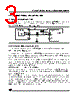
3 / 8 page  3/8 ST7 ROUTINE FOR I2C SLAVE MODE MANAGEMENT 2 ST7 I2C COMMUNICATION APPLICATION 2.1 HARDWARE CONFIGURATION The ST7 I2C communication application hardware is composed by a ST72264 microcontroller used as a slave which communicates with any master through an I2C bus interface. Figure 3. ST7 I2C Communication Application 2.2 ST7 I2C PERIPHERAL BASIC DRIVERS In this chapter all registers refer to the ST7 I2C peripheral ones (otherwise specified). 2.2.1 Initialize the I2C peripheral In this application the initialization of the ST7 I2C peripheral is done completely by software. First the Control register (CR) is cleared and the Data (DR) and Status (SR1,SR2) registers are touched to clear all possible pending event. Then, the peripheral is enabled through the Control register (CR). This action needs to write twice in the register due to the fact that the Control register (CR) bits can be set only when the PE enable bit is already set. To allow the peripheral to acknowledge the received data the ACK bit of the Control register (CR) is set. 2.2.2 Slave Communication on the I2C Bus First the interface frequency must be configured using the FRi bits in the OAR2 register.For 10 bit addressing mode, user must configure the slave address using the ADD9 and ADD8 bits of the OAR2 register. To initiate a I2C communication, first a start condition has to be generated and then the se- lected slave address has to be sent, both by the master. As soon as a start condition is de- tected, the address is received from the SDA line and sent to the shift register; then it is com- pared with the address of the interface (OAR1) or the General Call address (if selected by soft- ware). If the GCAL option is to be implemented, user must enable it by selecting the GCAL_Add in user customizable part of the code. ST72F264 I2C Vdd Vss SCL 5V 2x100 Ω SDA 2x27K Ω master SCL SDA Vss Vdd |
|
|
Lien URL |
| ALLDATASHEET vous a-t-il été utile ? [ DONATE ] |
À propos de Alldatasheet | Publicité | Contactez-nous | Politique de confidentialité | Lien vers la fiche technique | Echange de liens | Fabricants All Rights Reserved©Alldatasheet.com |
| Russian : Alldatasheetru.com | Korean : Alldatasheet.co.kr | Spanish : Alldatasheet.es | French : Alldatasheet.fr | Italian : Alldatasheetit.com Portuguese : Alldatasheetpt.com | Polish : Alldatasheet.pl | Vietnamese : Alldatasheet.vn Indian : Alldatasheet.in | Mexican : Alldatasheet.com.mx | British : Alldatasheet.co.uk | New Zealand : Alldatasheet.co.nz |
|
Family Site : ic2ic.com |
icmetro.com |
 French ▼
 English
 Chinese
 German
 Japanese
 Russian
 Korean
 Spanish
 French
 Italian
 Portuguese
 Polish
 Vietnamese
 Indian
 Mexican
 British
 New Zealand