|
Moteur de recherche de fiches techniques de composants électroniques |
|
|
Moteur de recherche de fiches techniques de composants électroniques |
|
AD8432ACPZ-R7 Fiches technique(PDF) 5 Page - Analog Devices |
|
|
|||||||||||||||||||||||||||||
AD8432ACPZ-R7 Fiches technique(HTML) 5 Page - Analog Devices |
|
|
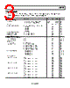
5 / 28 page  AD8432 Rev. 0 | Page 5 of 28 ABSOLUTE MAXIMUM RATINGS MAXIMUM POWER DISSIPATION Table 2. Parameter Rating Voltage Supply Voltage 5.5 V Input Voltage 0 V to VPS Power Dissipation 120 mW Temperature Operating Temperature –40°C to +85°C Storage Temperature –65°C to +150°C Package Glass Transition Temperature (TG) 150°C Lead Temperature (Soldering, 60 sec) 300°C The maximum safe power dissipation for the AD8432 is limited by the associated rise in junction temperature (TJ) on the die. At approximately 150°C, which is the glass transition temperature, the properties of the plastic change. Even temporarily exceeding this temperature limit may change the stresses that the package exerts on the die, permanently shifting the parametric performance of the amplifiers. Exceeding a temperature of 150°C for an extended period can cause changes in silicon devices, potentially resulting in a loss of functionality. ESD CAUTION Stresses above those listed under Absolute Maximum Ratings may cause permanent damage to the device. This is a stress rating only; functional operation of the device at these or any other conditions above those indicated in the operational section of this specification is not implied. Exposure to absolute maximum rating conditions for extended periods may affect device reliability. THERMAL RESISTANCE θJA is specified for the worst-case conditions, that is, a device soldered in a circuit board for surface-mount packages. The θJA values in Table 3 assume a 4-layer JEDEC standard board with zero airflow. Table 3. Thermal Resistance1 Parameter θJA θJC θJB ΨJT Unit 40-Lead LFCSP 57.9 11.2 35.9 1.1 °C/W 1 4-Layer JEDEC board (2S2P). |
|
Lien URL |
| ALLDATASHEET vous a-t-il été utile ? [ DONATE ] |
À propos de Alldatasheet | Publicité | Contactez-nous | Politique de confidentialité | Lien vers la fiche technique | Echange de liens | Fabricants All Rights Reserved©Alldatasheet.com |
| Russian : Alldatasheetru.com | Korean : Alldatasheet.co.kr | Spanish : Alldatasheet.es | French : Alldatasheet.fr | Italian : Alldatasheetit.com Portuguese : Alldatasheetpt.com | Polish : Alldatasheet.pl | Vietnamese : Alldatasheet.vn Indian : Alldatasheet.in | Mexican : Alldatasheet.com.mx | British : Alldatasheet.co.uk | New Zealand : Alldatasheet.co.nz |
|
Family Site : ic2ic.com |
icmetro.com |
 French ▼
 English
 Chinese
 German
 Japanese
 Russian
 Korean
 Spanish
 French
 Italian
 Portuguese
 Polish
 Vietnamese
 Indian
 Mexican
 British
 New Zealand