|
Moteur de recherche de fiches techniques de composants électroniques |
|
|
Moteur de recherche de fiches techniques de composants électroniques |
|
MF602F Fiches technique(PDF) 7 Page - List of Unclassifed Manufacturers |
|
|
|||||||||||||||||||||||||||||
MF602F Fiches technique(HTML) 7 Page - List of Unclassifed Manufacturers |
|
|
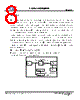
7 / 11 page  Product Specification MF602F Data sheet subject to change without notice RDPS-MF017(R1)03/04/2002 SHEET 7 OF 11 4.3 : DC characteristic : All requirement of this specification can be met in the presence of all POTS loop currents from 0mA to 100mA. This in line filter can pass POTS tip-to-ring dc voltages of 0V to 105V and ringing signals of 40V to 150Vrms at any frequency from15.3Hz to 68Hz with a DC component in the range from 0V to 105V. The dc resistance from tip-to-ring at the line port interface with the phone interface shorted, shall be less than or equal to 15 ohms for one splitter.The DC resistance from tip-to-ground and from ring-to-ground at the POTS interface with the U-R interface open shall be greater than or equal to5 Megohms. The ground point shall be local building or green wire ground. As an objective , the DC resistance should exceed 10M Ω. 4.4 : Test method : 4.4.1 : Insertion loss : The insertion loss of a device connected into a given transmission system is defined as the ratio, expressed in dB, of the load power available(before and after insertion ) delivered to the output network beyond the point of insertion at a given frequency.In general , the insertion loss is defined as the ratio, expressed in dB of the power delivered to a load with the circuit in place and the power delivered to a load without the circuit in place.The added insertion loss shall be measured using the test up in figure 3. For measuring POTS band insertion loss for single filter module also a single filter wit four added parallel load filters.General Insertion loss equation can be expressed as following Insertion loss = 20 log V2 / V1 dB where V1 = the measured voltage value of load without LPF in circuit. V2 = the measured voltage value of load with LPF in circuit. The test setup is shown in drawing below. : ZL LPF Equipment ZL Phone Line Load#1 LPF Load#4 LPF Remote POTS Splitter ZL is normal Termination in test set Test |
|
|
Lien URL |
| ALLDATASHEET vous a-t-il été utile ? [ DONATE ] |
À propos de Alldatasheet | Publicité | Contactez-nous | Politique de confidentialité | Lien vers la fiche technique | Echange de liens | Fabricants All Rights Reserved©Alldatasheet.com |
| Russian : Alldatasheetru.com | Korean : Alldatasheet.co.kr | Spanish : Alldatasheet.es | French : Alldatasheet.fr | Italian : Alldatasheetit.com Portuguese : Alldatasheetpt.com | Polish : Alldatasheet.pl | Vietnamese : Alldatasheet.vn Indian : Alldatasheet.in | Mexican : Alldatasheet.com.mx | British : Alldatasheet.co.uk | New Zealand : Alldatasheet.co.nz |
|
Family Site : ic2ic.com |
icmetro.com |
 French ▼
 English
 Chinese
 German
 Japanese
 Russian
 Korean
 Spanish
 French
 Italian
 Portuguese
 Polish
 Vietnamese
 Indian
 Mexican
 British
 New Zealand