|
Moteur de recherche de fiches techniques de composants électroniques |
|
|
Moteur de recherche de fiches techniques de composants électroniques |
|
ATS668LSM Fiches technique(PDF) 5 Page - Allegro MicroSystems |
|
|
|||||||||||||||||||||||||||||
ATS668LSM Fiches technique(HTML) 5 Page - Allegro MicroSystems |
|
|
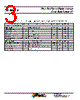
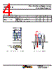
5 / 13 page  True Zero-Speed High-Accuracy Gear Tooth Sensor IC ATS668LSM 5 Allegro MicroSystems, LLC 115 Northeast Cutoff Worcester, Massachusetts 01615-0036 U.S.A. 1.508.853.5000; www.allegromicro.com FUNCTIONAL CHARACTERISTICS Characteristics Symbol Note Min. Typ. Max. Unit POWER ON Power-On State POS VOUT state at t > tPO; see Figure 1 – High – – Power-On Time [1] tPO fop < 100 Hz – – 2 ms AIR GAP Operating Air Gap Range Guaranteed to operate within specification 0.5 – 2.5 mm Extended Air Gap Range Switching only—not guaranteed to operate within spec 2.5 – 3 mm OFFSET Dynamic Offset Cancellation BDIFFEXT Allowable user-induced offset ±60 – – G CALIBRATION Initial Calibration [2] CALI Quantity of rising output edges required for accurate edge detection – 2 3 edge SWITCHING Operating Speed fOP 0 – 12 kHz Analog Signal Bandwidth BW 15 20 – kHz Operate Point OP – 70 – % Release Point RP – 30 – % OUTPUT DUTY CYCLE [3] Output Duty Cycle DC AG = 0.5 mm to 2.5 mm, Pin 3 to 1 target rotation 39 – 52 % AG = 2.5 mm to 3.0 mm, Pin 3 to 1 target rotation 39 – 56 % 1 Power-On Time includes the time required to complete the internal automatic offset adjust. DAC is then ready for peak acquisition. 2 For power-on frequency, fOP < 200 Hz. Higher power-on frequencies may result in more input magnetic cycles until full output edge accuracy is achieved, including the possibility of missed output edges. 3 Measured at fOP = 2 kHz. Output rise and fall times should be considered when measuring duty cycle. Figure 4: Definition of Terms for Switchpoints Valley Tooth Forward Reverse +B –B +V –V t BOP(FWD)b VPROC(BOP) VPROC(BRP) BRP(FWD) BOP % BRP % 100 % BOP(REV)b BRP(REV) Sensed Edgea aSensed Edge: leading (rising) mechanical edge in forward rotation, trailing (falling) mechanical edge in reverse rotation bBOP(FWD) triggers the output transition during forward rotation, and BOP(REV) triggers the output transition during reverse rotation |
|
|
Lien URL |
| ALLDATASHEET vous a-t-il été utile ? [ DONATE ] |
À propos de Alldatasheet | Publicité | Contactez-nous | Politique de confidentialité | Lien vers la fiche technique | Echange de liens | Fabricants All Rights Reserved©Alldatasheet.com |
| Russian : Alldatasheetru.com | Korean : Alldatasheet.co.kr | Spanish : Alldatasheet.es | French : Alldatasheet.fr | Italian : Alldatasheetit.com Portuguese : Alldatasheetpt.com | Polish : Alldatasheet.pl | Vietnamese : Alldatasheet.vn Indian : Alldatasheet.in | Mexican : Alldatasheet.com.mx | British : Alldatasheet.co.uk | New Zealand : Alldatasheet.co.nz |
|
Family Site : ic2ic.com |
icmetro.com |
 French ▼
 English
 Chinese
 German
 Japanese
 Russian
 Korean
 Spanish
 French
 Italian
 Portuguese
 Polish
 Vietnamese
 Indian
 Mexican
 British
 New Zealand