 |
Moteur de recherche de fiches techniques de composants électroniques |
|
|
Moteur de recherche de fiches techniques de composants électroniques |
|
The question interval is too short.
Please try again in a few seconds.

Hello, Please ask a question about CM494CP Datasheet
# Example questions:
➢ What is the typical breakdown voltage of the zener diode circuit (uc495a) when the collector voltage (vcc) is 45v and the zener current (lz) is 2ma?
➢ What is the function of pin 1 on the device?
➢ The datasheet lists several switching characteristics, including output voltage rise time and fall time. under what configuration does the datasheet specify an output voltage rise time of approximately 100-200ns?
| Part No. | CM494CP |
| Manufacturer | ETC |
| Size | 512 Kbytes |
| Pages | 9 pages |
| Description | ADVANCED REGULATING PULSE WIDTH MODULATOR |


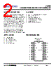


1. Core Functionality:
️· What it is: The CM494 is a PWM controller. It's designed to regulate voltage and current in power supply applications. It likely controls switching transistors (like MOSFETs or BJTs) to adjust the output voltage based on feedback.
️· Key Features:
- Advanced PWM: Implies sophisticated control algorithms (possibly including features like soft start, overcurrent protection, frequency variation, etc.)
- Steering Control: Indicates that the IC has internal circuitry to drive external power transistors efficiently.
- Zener Diode Circuit (UC495A only): Suggests a specific version (UC495A) has built-in overvoltage protection.
️· Applications: This IC is probably used in switched-mode power supplies (SMPS), DC-DC converters, and similar applications.
2. Electrical Characteristics (Most Important Section):
This is where the detailed specifications are found. Here's a summarized breakdown (note that there's *a lot* of data here, so this is not exhaustive). Units are generally Volts (V), Amps (A), Hertz (Hz), or Milliseconds (ms).
️· Supply Voltage: Seems to operate from approximately 3.5V to 40V, with an under-voltage lockout (UVLO) voltage around 3.5-6.5V.
️· Frequency: Determined by external components (RT and CT) as f ≈ 1.1 / (RT * CT)
️· Comparator Inputs: Requires around 4V at comparator input for switching.
️· Output Transistors: Includes Saturation Voltages (VCE(sat) and VCE(sat) in emitter-follower mode), with ranges for Collector Off-State Current (2-100µA) and Emitter Off-State Current (-100 µA)
️· PWM Comparator: Switching times are defined (rise and fall times, 25-200ns).
️· Steering Control: Has inputs current range of -200µA to +300µA
️· Switching Speed: The device has reasonable switching speed (rise/fall times in the nanosecond range).
3. Pin Descriptions (Refer to page 6. Not reproduced in full here due to length, but critical for understanding how to use the chip.)
4. Typical Characteristics & Graphs (Pages 8 onwards. Not reproduced. These show how the circuit behaves under different conditions, providing a deeper understanding.)
5. Mechanical Details (Page 5) Includes information on package types (likely DIP or similar) and dimensions.
Key Takeaways & Implications for Use:
️· Component Selection: The external resistor (RT) and capacitor (CT) values significantly impact the operating frequency of the PWM.
️· Power Transistor Drive: The steering control circuitry simplifies the design of the power stage, but care must be taken to match the drive characteristics to the selected transistors.
️· Overvoltage Protection: The UC495A version has built-in overvoltage protection, which is beneficial for safety and reliability.
️· Thermal Considerations: As with any power IC, proper heat sinking might be required depending on the load conditions.
1. Core Functionality:
️· What it is: The CM494 is a PWM controller. It's designed to regulate voltage and current in power supply applications. It likely controls switching transistors (like MOSFETs or BJTs) to adjust the output voltage based on feedback.
️· Key Features:
- Advanced PWM: Implies sophisticated control algorithms (possibly including features like soft start, overcurrent protection, frequency variation, etc.)
- Steering Control: Indicates that the IC has internal circuitry to drive external power transistors efficiently.
- Zener Diode Circuit (UC495A only): Suggests a specific version (UC495A) has built-in overvoltage protection.
️· Applications: This IC is probably used in switched-mode power supplies (SMPS), DC-DC converters, and similar applications.
2. Electrical Characteristics (Most Important Section):
This is where the detailed specifications are found. Here's a summarized breakdown (note that there's *a lot* of data here, so this is not exhaustive). Units are generally Volts (V), Amps (A), Hertz (Hz), or Milliseconds (ms).
️· Supply Voltage: Seems to operate from approximately 3.5V to 40V, with an under-voltage lockout (UVLO) voltage around 3.5-6.5V.
️· Frequency: Determined by external components (RT and CT) as f ≈ 1.1 / (RT * CT)
️· Comparator Inputs: Requires around 4V at comparator input for switching.
️· Output Transistors: Includes Saturation Voltages (VCE(sat) and VCE(sat) in emitter-follower mode), with ranges for Collector Off-State Current (2-100µA) and Emitter Off-State Current (-100 µA)
️· PWM Comparator: Switching times are defined (rise and fall times, 25-200ns).
️· Steering Control: Has inputs current range of -200µA to +300µA
️· Switching Speed: The device has reasonable switching speed (rise/fall times in the nanosecond range).
3. Pin Descriptions (Refer to page 6. Not reproduced in full here due to length, but critical for understanding how to use the chip.)
4. Typical Characteristics & Graphs (Pages 8 onwards. Not reproduced. These show how the circuit behaves under different conditions, providing a deeper understanding.)
5. Mechanical Details (Page 5) Includes information on package types (likely DIP or similar) and dimensions.
Key Takeaways & Implications for Use:
️· Component Selection: The external resistor (RT) and capacitor (CT) values significantly impact the operating frequency of the PWM.
️· Power Transistor Drive: The steering control circuitry simplifies the design of the power stage, but care must be taken to match the drive characteristics to the selected transistors.
️· Overvoltage Protection: The UC495A version has built-in overvoltage protection, which is beneficial for safety and reliability.
️· Thermal Considerations: As with any power IC, proper heat sinking might be required depending on the load conditions.
| Part No. | CM494CP |
| Manufacturer | ETC |
| Size | 512 Kbytes |
| Pages | 9 pages |
| Description | ADVANCED REGULATING PULSE WIDTH MODULATOR |
| ALLDATASHEET vous a-t-il été utile ? [ DONATE ] |
À propos de Alldatasheet | Publicité | Contactez-nous | Politique de confidentialité | Lien vers la fiche technique | Echange de liens | Fabricants All Rights Reserved©Alldatasheet.com |
| Russian : Alldatasheetru.com | Korean : Alldatasheet.co.kr | Spanish : Alldatasheet.es | French : Alldatasheet.fr | Italian : Alldatasheetit.com Portuguese : Alldatasheetpt.com | Polish : Alldatasheet.pl | Vietnamese : Alldatasheet.vn Indian : Alldatasheet.in | Mexican : Alldatasheet.com.mx | British : Alldatasheet.co.uk | New Zealand : Alldatasheet.co.nz |
|
Family Site : ic2ic.com |
icmetro.com |
 French ▼
  English
 Chinese
 German
 Japanese
 Russian
 Korean
 Spanish
 Italian
 Portuguese
 Polish
 Vietnamese
 Indian
 Mexican
 British
 New Zealand