 |
Moteur de recherche de fiches techniques de composants électroniques |
|
|
Moteur de recherche de fiches techniques de composants électroniques |
|
The question interval is too short.
Please try again in a few seconds.

Hello, Please ask a question about LT1161 Datasheet
# Example questions:
➢ What is the primary benefit of using pcb traces as drain sense resistors?
➢ What component (and value) is suggested to control the restart period of the lt1161?
➢ What is the purpose of this network and how does it function?
| Part No. | LT1161 |
| Manufacturer | LINER |
| Size | 290 Kbytes |
| Pages | 12 pages |
| Description | Quad Protected High-Side MOSFET Driver |


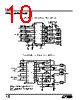


Okay, let's break down the content you've provided. This document is a comprehensive application guide for the LT1161, a power MOSFET controller with current sensing and automatic restart capabilities. Here's a structured summary, highlighting key areas:
1. Overview & Functionality:
️· The LT1161 is a power MOSFET controller.
️· It incorporates current sensing to protect against overcurrent conditions.
️· It has an automatic restart feature, designed to recover from short-term overloads.
️· It's aimed at applications requiring controlled power MOSFET switching.
2. Key Features & Benefits:
️· Current Sensing: Uses supply-referenced current sensing for accuracy.
️· Automatic Restart: Provides self-recovery from overcurrent events (with a defined restart period).
️· Flexibility: Supports different load types (inductive and capacitive) with appropriate configurations.
️· PCB Shunt Resistors: Allows the use of printed circuit board traces as drain sense resistors, eliminating the need for separate components.
️· Input Isolation: Facilitates isolation from control logic using opto-isolators.
3. Applications and Configuration Details:
️· Drain Sense Configuration: Describes proper connection of drain sense resistors to the LT1161 for accurate current sensing. Crucially emphasizes that the V+ pins (pins 11 and 20) must be connected to the positive side of the sense resistors *and* to each other.
️· Inductive vs. Capacitive Loads:
- Inductive: A clamp diode is recommended to handle current decay when turning off.
- Capacitive: A network is needed to control the initial surge current (∂V/∂t) to prevent false tripping of the current limit.
️· Automatic Restart Period Control: The timing capacitor (C<sub>T</sub>) determines the length of the restart period.
️· Defeating Automatic Restart: Explains how to disable the automatic restart feature for applications that require a latched-off state after a fault.
️· Current Limit Delay Network: Describes how to add a delay network in the current sensing path to prevent false tripping in noisy environments or when switching capacitive loads.
️· PCB Shunt Resistors: Provides guidance on using PCB traces as drain sense resistors, based on copper thickness and current requirements.
4. Important Considerations & Best Practices:
️· Input/Supply Sequencing: No specific sequencing requirements, but the input can be active even when the supply voltage is zero.
️· Input Isolation: Use opto-isolators for protection in harsh environments.
️· Kelvin Connections: Essential when using PCB shunts to minimize voltage drops.
️· Temperature Coefficients: Utilizing the temperature coefficient of PCB traces for current sensing can offer advantages.
️· Supply Decoupling: Decoupling capacitors are important for high input voltages.
Overall, the document is a detailed guide for implementing and optimizing the LT1161 in various power control applications, providing essential configuration details, troubleshooting tips, and design considerations.
1. Overview & Functionality:
️· The LT1161 is a power MOSFET controller.
️· It incorporates current sensing to protect against overcurrent conditions.
️· It has an automatic restart feature, designed to recover from short-term overloads.
️· It's aimed at applications requiring controlled power MOSFET switching.
2. Key Features & Benefits:
️· Current Sensing: Uses supply-referenced current sensing for accuracy.
️· Automatic Restart: Provides self-recovery from overcurrent events (with a defined restart period).
️· Flexibility: Supports different load types (inductive and capacitive) with appropriate configurations.
️· PCB Shunt Resistors: Allows the use of printed circuit board traces as drain sense resistors, eliminating the need for separate components.
️· Input Isolation: Facilitates isolation from control logic using opto-isolators.
3. Applications and Configuration Details:
️· Drain Sense Configuration: Describes proper connection of drain sense resistors to the LT1161 for accurate current sensing. Crucially emphasizes that the V+ pins (pins 11 and 20) must be connected to the positive side of the sense resistors *and* to each other.
️· Inductive vs. Capacitive Loads:
- Inductive: A clamp diode is recommended to handle current decay when turning off.
- Capacitive: A network is needed to control the initial surge current (∂V/∂t) to prevent false tripping of the current limit.
️· Automatic Restart Period Control: The timing capacitor (C<sub>T</sub>) determines the length of the restart period.
️· Defeating Automatic Restart: Explains how to disable the automatic restart feature for applications that require a latched-off state after a fault.
️· Current Limit Delay Network: Describes how to add a delay network in the current sensing path to prevent false tripping in noisy environments or when switching capacitive loads.
️· PCB Shunt Resistors: Provides guidance on using PCB traces as drain sense resistors, based on copper thickness and current requirements.
4. Important Considerations & Best Practices:
️· Input/Supply Sequencing: No specific sequencing requirements, but the input can be active even when the supply voltage is zero.
️· Input Isolation: Use opto-isolators for protection in harsh environments.
️· Kelvin Connections: Essential when using PCB shunts to minimize voltage drops.
️· Temperature Coefficients: Utilizing the temperature coefficient of PCB traces for current sensing can offer advantages.
️· Supply Decoupling: Decoupling capacitors are important for high input voltages.
Overall, the document is a detailed guide for implementing and optimizing the LT1161 in various power control applications, providing essential configuration details, troubleshooting tips, and design considerations.
| Part No. | LT1161 |
| Manufacturer | LINER |
| Size | 290 Kbytes |
| Pages | 12 pages |
| Description | Quad Protected High-Side MOSFET Driver |
| ALLDATASHEET vous a-t-il été utile ? [ DONATE ] |
À propos de Alldatasheet | Publicité | Contactez-nous | Politique de confidentialité | Lien vers la fiche technique | Echange de liens | Fabricants All Rights Reserved©Alldatasheet.com |
| Russian : Alldatasheetru.com | Korean : Alldatasheet.co.kr | Spanish : Alldatasheet.es | French : Alldatasheet.fr | Italian : Alldatasheetit.com Portuguese : Alldatasheetpt.com | Polish : Alldatasheet.pl | Vietnamese : Alldatasheet.vn Indian : Alldatasheet.in | Mexican : Alldatasheet.com.mx | British : Alldatasheet.co.uk | New Zealand : Alldatasheet.co.nz |
|
Family Site : ic2ic.com |
icmetro.com |
 French ▼
  English
 Chinese
 German
 Japanese
 Russian
 Korean
 Spanish
 Italian
 Portuguese
 Polish
 Vietnamese
 Indian
 Mexican
 British
 New Zealand