 |
Moteur de recherche de fiches techniques de composants électroniques |
|
|
Moteur de recherche de fiches techniques de composants électroniques |
|
The question interval is too short.
Please try again in a few seconds.

Hello, Please ask a question about MCP6231 Datasheet
# Example questions:
➢ What is the approximate input bias current at a temperature of +85°c?
➢ What is the typical thermal resistance (θja) for the mcp6231/1r/1u/2/4 package type 8l-tdfn?
➢ What is the maximum junction temperature (tj) that the mcp6231/1r/1u/2/4 can reach without exceeding its absolute maximum ratings?
| Part No. | MCP6231 |
| Manufacturer | MICROCHIP |
| Size | 850 Kbytes |
| Pages | 40 pages |
| Description | 20 關A, 300 kHz Rail-to-Rail Op Amp |






1. General Information:
️· Device: MCP6231/1R/1U/2/4 (Operational Amplifier)
️· Datasheet Section: This extract comes from sections covering Typical Performance Curves and related test conditions.
️· Standard Test Conditions (Unless otherwise specified):
- V<sub>DD</sub> = 1.8V to 5.5V
- V<sub>SS</sub> = Ground (GND)
- V<sub>CM</sub> (Common-Mode Voltage) = V<sub>DD</sub>/2 or V<sub>SS</sub> (as specified in individual figures)
- V<sub>OUT</sub> ≈ V<sub>DD</sub>/2 (output voltage close to the common mode voltage)
- R<sub>L</sub> (Load Resistance) = 100 kΩ to V<sub>DD</sub>/2
- C<sub>L</sub> (Load Capacitance) = 60 pF
- T<sub>A</sub> (Ambient Temperature) = +25°C, unless otherwise noted.
2. Electrical Characteristics (from figures and mentions):
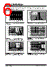
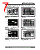
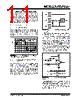
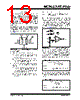
️· Input Offset Voltage (VOS): A graph shows input offset voltage as a function of ambient temperature (Figure 2-1).
️· Input Bias Current (IB): Graphs show input bias current at +85°C (Figure 2-3) and +125°C (Figure 2-6).
️· Power Supply Rejection Ratio (PSRR): Graphs show PSRR versus frequency, with and without the condition VCM = VSS (Figure 5-2).
️· Common-Mode Rejection Ratio (CMRR): Graphs show CMRR versus frequency, with the condition VCM = VSS (Figure 2-4).
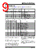
️· Short Circuit Output Current (I<sub>SC</sub>): Values are shown in a table for various temperatures and supply voltages.
3. Performance Curves Details & Observations
️· Input Offset Voltage: Shows that VOS varies with temperature (graphical representation).
️· Input Bias Current: Shows that IB increases with temperature (graphical representation).
️· PSRR & CMRR: Performance degrades at higher frequencies. PSRR is affected by the common-mode voltage (dependent on whether VCM = VSS or another condition).
️· Open-Loop Gain & Phase: (Figure 2-5) - Shows the relationship of gain and phase vs. frequency.
️· Short Circuit Output Current Increases with increasing temperature.
4. Thermal Characteristics:
️· Junction Temperature Limit: The internal junction temperature (T<sub>J</sub>) must not exceed +150°C.
️· Thermal Resistance (θJA) Values: Provided for various package types:
- 5L-SC70: 331 °C/W
- 5L-SOT-23: 256 °C/W
- 8L-DFN: 84.5 °C/W
- 8L-MSOP: 206 °C/W
- 8L-TDFN: 41 °C/W
- 8L-PDIP: 85 °C/W
- 8L-SOIC: 163 °C/W
- 14L-PDIP: 70 °C/W
- 14L-SOIC: 120 °C/W
- 14L-TSSOP: 100 °C/W
5. Test Circuits:
️· Figure 1-1 and Figure 1-2 show AC and DC Test circuits (most non-inverting and inverting gain conditions respectively).
️· Surface leakage rules apply (mention of Section 4.6).
Important Considerations:
️· Graphical Data: Many characteristics are described graphically. You're meant to analyze the trends and relationships displayed in those figures.
️· Specific Conditions: Always pay attention to the specific test conditions listed for each figure or table (voltage levels, temperature, etc.).
️· Complete Datasheet: This is an excerpt. Refer to the full datasheet for a comprehensive understanding of the device's specifications and application guidelines.
1. General Information:
️· Device: MCP6231/1R/1U/2/4 (Operational Amplifier)
️· Datasheet Section: This extract comes from sections covering Typical Performance Curves and related test conditions.
️· Standard Test Conditions (Unless otherwise specified):
- V<sub>DD</sub> = 1.8V to 5.5V
- V<sub>SS</sub> = Ground (GND)
- V<sub>CM</sub> (Common-Mode Voltage) = V<sub>DD</sub>/2 or V<sub>SS</sub> (as specified in individual figures)
- V<sub>OUT</sub> ≈ V<sub>DD</sub>/2 (output voltage close to the common mode voltage)
- R<sub>L</sub> (Load Resistance) = 100 kΩ to V<sub>DD</sub>/2
- C<sub>L</sub> (Load Capacitance) = 60 pF
- T<sub>A</sub> (Ambient Temperature) = +25°C, unless otherwise noted.
2. Electrical Characteristics (from figures and mentions):
️· Input Offset Voltage (VOS): A graph shows input offset voltage as a function of ambient temperature (Figure 2-1).
️· Input Bias Current (IB): Graphs show input bias current at +85°C (Figure 2-3) and +125°C (Figure 2-6).
️· Power Supply Rejection Ratio (PSRR): Graphs show PSRR versus frequency, with and without the condition VCM = VSS (Figure 5-2).
️· Common-Mode Rejection Ratio (CMRR): Graphs show CMRR versus frequency, with the condition VCM = VSS (Figure 2-4).
️· Short Circuit Output Current (I<sub>SC</sub>): Values are shown in a table for various temperatures and supply voltages.
3. Performance Curves Details & Observations
️· Input Offset Voltage: Shows that VOS varies with temperature (graphical representation).
️· Input Bias Current: Shows that IB increases with temperature (graphical representation).
️· PSRR & CMRR: Performance degrades at higher frequencies. PSRR is affected by the common-mode voltage (dependent on whether VCM = VSS or another condition).
️· Open-Loop Gain & Phase: (Figure 2-5) - Shows the relationship of gain and phase vs. frequency.
️· Short Circuit Output Current Increases with increasing temperature.
4. Thermal Characteristics:
️· Junction Temperature Limit: The internal junction temperature (T<sub>J</sub>) must not exceed +150°C.
️· Thermal Resistance (θJA) Values: Provided for various package types:
- 5L-SC70: 331 °C/W
- 5L-SOT-23: 256 °C/W
- 8L-DFN: 84.5 °C/W
- 8L-MSOP: 206 °C/W
- 8L-TDFN: 41 °C/W
- 8L-PDIP: 85 °C/W
- 8L-SOIC: 163 °C/W
- 14L-PDIP: 70 °C/W
- 14L-SOIC: 120 °C/W
- 14L-TSSOP: 100 °C/W
5. Test Circuits:
️· Figure 1-1 and Figure 1-2 show AC and DC Test circuits (most non-inverting and inverting gain conditions respectively).
️· Surface leakage rules apply (mention of Section 4.6).
Important Considerations:
️· Graphical Data: Many characteristics are described graphically. You're meant to analyze the trends and relationships displayed in those figures.
️· Specific Conditions: Always pay attention to the specific test conditions listed for each figure or table (voltage levels, temperature, etc.).
️· Complete Datasheet: This is an excerpt. Refer to the full datasheet for a comprehensive understanding of the device's specifications and application guidelines.
| Part No. | MCP6231 |
| Manufacturer | MICROCHIP |
| Size | 850 Kbytes |
| Pages | 40 pages |
| Description | 20 關A, 300 kHz Rail-to-Rail Op Amp |
| ALLDATASHEET vous a-t-il été utile ? [ DONATE ] |
À propos de Alldatasheet | Publicité | Contactez-nous | Politique de confidentialité | Lien vers la fiche technique | Echange de liens | Fabricants All Rights Reserved©Alldatasheet.com |
| Russian : Alldatasheetru.com | Korean : Alldatasheet.co.kr | Spanish : Alldatasheet.es | French : Alldatasheet.fr | Italian : Alldatasheetit.com Portuguese : Alldatasheetpt.com | Polish : Alldatasheet.pl | Vietnamese : Alldatasheet.vn Indian : Alldatasheet.in | Mexican : Alldatasheet.com.mx | British : Alldatasheet.co.uk | New Zealand : Alldatasheet.co.nz |
|
Family Site : ic2ic.com |
icmetro.com |
 French ▼
  English
 Chinese
 German
 Japanese
 Russian
 Korean
 Spanish
 Italian
 Portuguese
 Polish
 Vietnamese
 Indian
 Mexican
 British
 New Zealand