 |
Moteur de recherche de fiches techniques de composants électroniques |
|
|
Moteur de recherche de fiches techniques de composants électroniques |
|
The question interval is too short.
Please try again in a few seconds.

Hello, Please ask a question about 24FC128 Datasheet
# Example questions:
➢ Explain the role of the acknowledge signal in the data transfer process and what action the slave device takes if the master does *not* generate an acknowledge bit during a read operation.
➢ How can multiple 24xx128 devices be used to expand the contiguous address space on the same bus, and what limitations apply to the msop package in this scenario?
➢ What bus conditions signify the start and stop of data transfer?
| Part No. | 24FC128 |
| Manufacturer | MICROCHIP |
| Size | 618 Kbytes |
| Pages | 32 pages |
| Description | 128K I2C??CMOS Serial EEPROM |





1. General Overview & Device Description
️· Device: The document describes the 24XX128 EEPROM (Electrically Erasable Programmable Read-Only Memory). It’s a memory chip designed for storing data that can be erased and reprogrammed electrically.
️· Interface: Uses a 2-wire serial bus, a common protocol for connecting multiple devices using minimal pins.
️· Addressing: Supports multiple devices on the same bus using address pins (A0, A1, A2).
️· Packages: Available in various packages (including MSOP), which affects the number of addressable devices.
️· Functionality: Designed for non-volatile data storage (data remains even when power is removed).
2. Bus Characteristics & Protocol
️· Data Transfer: Controlled by a "master" device that generates the clock signal (SCL). The EEPROM acts as a "slave."
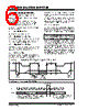
️· Start/Stop Conditions: Specific transitions on the SDA (Serial Data) line during high periods of the SCL signal define the start and end of data transfers.
️· Acknowledge (ACK): Each receiving device acknowledges successful reception of data with a signal on the SDA line.
️· Addressing: Requires a control byte (defined below) to specify device selection and operation type.
3. Control Byte Structure
The control byte is the first byte sent after the Start condition. It's critical for communication.
️· Structure:
- Start Bit: 1
- Device Select Code: 1010 (fixed)
- Chip Select Bits (A2, A1, A0): Used to select a specific EEPROM on the bus. Must match the actual logic levels on the A0, A1, and A2 pins of the selected EEPROM.
- Read/Write (R/W) Bit:
■ `0`: Write operation
■ `1`: Read operation
- ACK Bit Used for acknowledge signal
4. Addressing and Memory Organization
️· Memory Size: 128 Kbit (16 KByte)
️· Contiguous Addressing: Multiple EEPROMs can be linked to create a larger address space, but you can't directly read across device boundaries.
️· MSOP Package Limitation: When using the MSOP package, only two devices can be connected, and the A0 and A1 address bits of the control byte must always be '0'.
5. Key Features & Considerations
️· Non-Volatile Storage: Data retention even without power.
️· Electrical Erasure & Programming: Data can be erased and reprogrammed electrically.
️· Serial Communication: Efficient for connecting multiple devices.
️· Address Pins: Used for device selection in multi-device systems.
️· MSOP Limitations: Reduced addressability and address bit restrictions.
1. General Overview & Device Description
️· Device: The document describes the 24XX128 EEPROM (Electrically Erasable Programmable Read-Only Memory). It’s a memory chip designed for storing data that can be erased and reprogrammed electrically.
️· Interface: Uses a 2-wire serial bus, a common protocol for connecting multiple devices using minimal pins.
️· Addressing: Supports multiple devices on the same bus using address pins (A0, A1, A2).
️· Packages: Available in various packages (including MSOP), which affects the number of addressable devices.
️· Functionality: Designed for non-volatile data storage (data remains even when power is removed).
2. Bus Characteristics & Protocol
️· Data Transfer: Controlled by a "master" device that generates the clock signal (SCL). The EEPROM acts as a "slave."
️· Start/Stop Conditions: Specific transitions on the SDA (Serial Data) line during high periods of the SCL signal define the start and end of data transfers.
️· Acknowledge (ACK): Each receiving device acknowledges successful reception of data with a signal on the SDA line.
️· Addressing: Requires a control byte (defined below) to specify device selection and operation type.
3. Control Byte Structure
The control byte is the first byte sent after the Start condition. It's critical for communication.
️· Structure:
- Start Bit: 1
- Device Select Code: 1010 (fixed)
- Chip Select Bits (A2, A1, A0): Used to select a specific EEPROM on the bus. Must match the actual logic levels on the A0, A1, and A2 pins of the selected EEPROM.
- Read/Write (R/W) Bit:
■ `0`: Write operation
■ `1`: Read operation
- ACK Bit Used for acknowledge signal
4. Addressing and Memory Organization
️· Memory Size: 128 Kbit (16 KByte)
️· Contiguous Addressing: Multiple EEPROMs can be linked to create a larger address space, but you can't directly read across device boundaries.
️· MSOP Package Limitation: When using the MSOP package, only two devices can be connected, and the A0 and A1 address bits of the control byte must always be '0'.
5. Key Features & Considerations
️· Non-Volatile Storage: Data retention even without power.
️· Electrical Erasure & Programming: Data can be erased and reprogrammed electrically.
️· Serial Communication: Efficient for connecting multiple devices.
️· Address Pins: Used for device selection in multi-device systems.
️· MSOP Limitations: Reduced addressability and address bit restrictions.
| Part No. | 24FC128 |
| Manufacturer | MICROCHIP |
| Size | 618 Kbytes |
| Pages | 32 pages |
| Description | 128K I2C??CMOS Serial EEPROM |
| ALLDATASHEET vous a-t-il été utile ? [ DONATE ] |
À propos de Alldatasheet | Publicité | Contactez-nous | Politique de confidentialité | Lien vers la fiche technique | Echange de liens | Fabricants All Rights Reserved©Alldatasheet.com |
| Russian : Alldatasheetru.com | Korean : Alldatasheet.co.kr | Spanish : Alldatasheet.es | French : Alldatasheet.fr | Italian : Alldatasheetit.com Portuguese : Alldatasheetpt.com | Polish : Alldatasheet.pl | Vietnamese : Alldatasheet.vn Indian : Alldatasheet.in | Mexican : Alldatasheet.com.mx | British : Alldatasheet.co.uk | New Zealand : Alldatasheet.co.nz |
|
Family Site : ic2ic.com |
icmetro.com |
 French ▼
  English
 Chinese
 German
 Japanese
 Russian
 Korean
 Spanish
 Italian
 Portuguese
 Polish
 Vietnamese
 Indian
 Mexican
 British
 New Zealand