 |
Moteur de recherche de fiches techniques de composants électroniques |
|
|
Moteur de recherche de fiches techniques de composants électroniques |
|
The question interval is too short.
Please try again in a few seconds.

Hello, Please ask a question about STDRIVE101 Datasheet
# Example questions:
➢ List all jumpers (j1-j7) and describe their physical configuration based on the provided data.
➢ What is the voltage rating of capacitor c5, and what is noted about its connection?
➢ Identify all components connected to pin 5 of u
| Part No. | STDRIVE101 |
| Manufacturer | STMICROELECTRONICS |
| Size | 959 Kbytes |
| Pages | 13 pages |
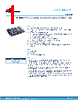
| Description | STDRIVE101 demonstration board for three-phase brushless motors |

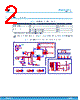
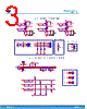
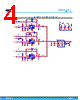
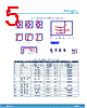
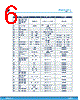
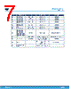

I. Core Component & Chip Details
️· U1: STDRV101: This is the central component - a motor driver IC. It appears to be a 3-phase motor driver.
II. Passive Components (Resistors, Capacitors)
️· Resistors:
- R1: 0 Ohm
- R2: 22k Ohm, 1% tolerance
- R3: 0 Ohm
- R4: 10k Ohm, 1% tolerance
- R5: 0 Ohm
- R6: 51k Ohm
- R7: 470 Ohm
- R8: 39k Ohm
- R9: 91k Ohm, 1% tolerance
️· Capacitors:
- C1: 1uF, 25V
- C2: 10nF
- C3: 1uF, 25V
- C4: 1uF, 25V
- C5: 1uF, 100V
- C6: 100nF, 100V
- C7: 4.7uF, 25V
- C8: 100nF, 25V
- C9: NM (likely not mounted, or a specific value not defined)
- C11: 100nF, 25V
III. Connectors & Mechanical
️· J1, J2, J3, J5, J6, J7: Various connectors. Their exact types aren't specified, but they're likely for power, signals, and motor connections.
️· J4: MC Connector: Motor Connector
️· Epad/GND: Indicates a thermal pad or connection for grounding, critical for the STDRV101's heat dissipation.
IV. STDRV101 Pin Assignments (as seen in the listing)
️· BOOT1: Pin 21
️· BOOT2: Pin 17
️· BOOT3: Pin 13
️· CP: Pin 1
️· DT_MODE: Pin 2
️· GHS1: Pin 22
️· GHS2: Pin 18
️· GHS3: Pin 14
️· GLS1: Pin 24
️· GLS2: Pin 20
️· GLS3: Pin 16
️· INH1_IN1: Pin 7
️· INH2_IN2: Pin 8
️· INH3_IN3: Pin 9
️· INL1_EN1: Pin 10
️· INL2_EN2: Pin 11
️· INL3_EN3: Pin 12
️· OUT1: Pin 23
️· OUT2: Pin 19
️· OUT3: Pin 15
️· REG12: Pin 5
️· SCREF: Pin 3
️· VS: Pin 4
️· nFAULT: Pin 6
V. Miscellaneous
️· LED1: Red LED
️· NM: Not mounted
Key Observations & Potential Functionality
️· Motor Driver: The STDRV101 and surrounding components clearly point to a 3-phase motor driver circuit.
️· Bootstrap Capacitors: The bootstrap capacitors (likely connected to the GHSx and GLSx pins) are essential for driving the high-side MOSFETs within the STDRV101.
️· Fault Protection: The nFAULT pin is for fault reporting, indicating overcurrent, overvoltage, or other error conditions.
️· Thermal Management: The Epad/GND connection is crucial for dissipating heat from the STDRV101, especially in higher-power applications.
I. Core Component & Chip Details
️· U1: STDRV101: This is the central component - a motor driver IC. It appears to be a 3-phase motor driver.
II. Passive Components (Resistors, Capacitors)
️· Resistors:
- R1: 0 Ohm
- R2: 22k Ohm, 1% tolerance
- R3: 0 Ohm
- R4: 10k Ohm, 1% tolerance
- R5: 0 Ohm
- R6: 51k Ohm
- R7: 470 Ohm
- R8: 39k Ohm
- R9: 91k Ohm, 1% tolerance
️· Capacitors:
- C1: 1uF, 25V
- C2: 10nF
- C3: 1uF, 25V
- C4: 1uF, 25V
- C5: 1uF, 100V
- C6: 100nF, 100V
- C7: 4.7uF, 25V
- C8: 100nF, 25V
- C9: NM (likely not mounted, or a specific value not defined)
- C11: 100nF, 25V
III. Connectors & Mechanical
️· J1, J2, J3, J5, J6, J7: Various connectors. Their exact types aren't specified, but they're likely for power, signals, and motor connections.
️· J4: MC Connector: Motor Connector
️· Epad/GND: Indicates a thermal pad or connection for grounding, critical for the STDRV101's heat dissipation.
IV. STDRV101 Pin Assignments (as seen in the listing)
️· BOOT1: Pin 21
️· BOOT2: Pin 17
️· BOOT3: Pin 13
️· CP: Pin 1
️· DT_MODE: Pin 2
️· GHS1: Pin 22
️· GHS2: Pin 18
️· GHS3: Pin 14
️· GLS1: Pin 24
️· GLS2: Pin 20
️· GLS3: Pin 16
️· INH1_IN1: Pin 7
️· INH2_IN2: Pin 8
️· INH3_IN3: Pin 9
️· INL1_EN1: Pin 10
️· INL2_EN2: Pin 11
️· INL3_EN3: Pin 12
️· OUT1: Pin 23
️· OUT2: Pin 19
️· OUT3: Pin 15
️· REG12: Pin 5
️· SCREF: Pin 3
️· VS: Pin 4
️· nFAULT: Pin 6
V. Miscellaneous
️· LED1: Red LED
️· NM: Not mounted
Key Observations & Potential Functionality
️· Motor Driver: The STDRV101 and surrounding components clearly point to a 3-phase motor driver circuit.
️· Bootstrap Capacitors: The bootstrap capacitors (likely connected to the GHSx and GLSx pins) are essential for driving the high-side MOSFETs within the STDRV101.
️· Fault Protection: The nFAULT pin is for fault reporting, indicating overcurrent, overvoltage, or other error conditions.
️· Thermal Management: The Epad/GND connection is crucial for dissipating heat from the STDRV101, especially in higher-power applications.
| Part No. | STDRIVE101 |
| Manufacturer | STMICROELECTRONICS |
| Size | 959 Kbytes |
| Pages | 13 pages |
| Description | STDRIVE101 demonstration board for three-phase brushless motors |
| ALLDATASHEET vous a-t-il été utile ? [ DONATE ] |
À propos de Alldatasheet | Publicité | Contactez-nous | Politique de confidentialité | Lien vers la fiche technique | Echange de liens | Fabricants All Rights Reserved©Alldatasheet.com |
| Russian : Alldatasheetru.com | Korean : Alldatasheet.co.kr | Spanish : Alldatasheet.es | French : Alldatasheet.fr | Italian : Alldatasheetit.com Portuguese : Alldatasheetpt.com | Polish : Alldatasheet.pl | Vietnamese : Alldatasheet.vn Indian : Alldatasheet.in | Mexican : Alldatasheet.com.mx | British : Alldatasheet.co.uk | New Zealand : Alldatasheet.co.nz |
|
Family Site : ic2ic.com |
icmetro.com |
 French ▼
  English
 Chinese
 German
 Japanese
 Russian
 Korean
 Spanish
 Italian
 Portuguese
 Polish
 Vietnamese
 Indian
 Mexican
 British
 New Zealand