 |
Moteur de recherche de fiches techniques de composants électroniques |
|
|
Moteur de recherche de fiches techniques de composants électroniques |
|
The question interval is too short.
Please try again in a few seconds.

Hello, Please ask a question about MP6539 Datasheet
# Example questions:
➢ The datasheet lists both qfn-28 and tssop packages. what are the primary advantages and disadvantages of each package type for a power electronics application?
➢ What is the purpose of the ocref pin and how does it relate to the device's protection features?
➢ How does the nsleep pin affect the device's power consumption, and what are the conditions for entering and exiting sleep mode?
| Part No. | MP6539 |
| Manufacturer | MPS |
| Size | 716 Kbytes |
| Pages | 15 pages |
| Description | 100V, Three-Phase, BLDC Motor Pre-Driver with HS & LS Inputs |


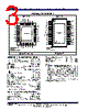


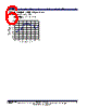

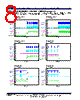


1. Overview & Function
️· What it is: The MP6539 is a high-voltage, three-phase gate driver designed for Brushless DC (BLDC) motor control applications.
️· Key Features:
- High voltage operation (up to 65V).
- Three independent driver channels (A, B, C).
- Bootstrap capability for high-side gate drive.
- Adjustable dead time.
- Overcurrent protection (OCP).
- Fault indication (nFAULT).
- Sleep mode for low-power operation (nSLEEP).
- LDO for base driving an external NPN transistor
2. Electrical Characteristics (Key Values)
️· Input Voltage (VIN): 12V to 65V
️· Gate Driver Supply Voltage (VREG): Typically 12V-20V (check datasheet for specifics).
️· Bootstrap Voltage (BST): Typically around 18V-20V, needs to be slightly higher than the gate voltage.
️· Output Drive Current: Each channel can provide up to ~2.5A (peak) for driving MOSFET gates.
️· Dead Time: Adjustable via the DT pin.
️· OCP Threshold: User-adjustable via the OCREF pin.
3. Pin Functions (Most Important)
️· VIN: Input supply voltage.
️· GND: Ground.
️· LSA, LSB, LSC: Low-side input signals for phases A, B, and C.
️· HSA, HSB, HSC: High-side input signals for phases A, B, and C.
️· GLA, GLB, GLC: Low-side gate drive outputs.
️· GHA, GHB, GHC: High-side gate drive outputs.
️· BSTA, BSTB, BSTC: Bootstrap outputs for high-side gate drive.
️· nFAULT: Fault output. Active-low – goes low when a fault condition is detected.
️· nSLEEP: Sleep mode input. Active-low.
️· OCREF: Overcurrent protection reference input. Used to set the OCP threshold.
️· DT: Dead time adjustment.
4. Operating Modes & Protection
️· Normal Operation: Driven by the low-side and high-side input signals.
️· Sleep Mode: Enabled by pulling nSLEEP low. Reduces power consumption.
️· Overcurrent Protection (OCP): Activated when the current exceeds a threshold set by OCREF.
️· Fault Indication (nFAULT): Signals faults like overcurrent, undervoltage, or other error conditions.
5. Key Design Considerations
️· Bootstrap Capacitors: Required for high-side gate drive. Their value depends on the MOSFET gate charge and switching frequency.
️· Dead Time Adjustment: Important to prevent shoot-through (both high-side and low-side transistors conducting simultaneously).
️· OCP Setting: Requires careful consideration of motor current and system requirements.
️· Layout: Proper PCB layout is crucial for minimizing noise and ensuring signal integrity, especially for high-speed switching applications.
️· Bootstrap Voltage: Must be sufficiently high to drive the high-side MOSFETs completely.
6. Summary of Figures and Diagrams (from the data sheet)
️· Typical Application Circuit: Shows how to connect the MP6539 with MOSFETs, bootstrap capacitors, resistors for OCP and dead time adjustments.
️· Timing Diagrams: Illustrate the gate drive signals, dead time, and fault indications.
️· Performance Graphs: Show the switching waveforms, drive currents, and efficiency.
1. Overview & Function
️· What it is: The MP6539 is a high-voltage, three-phase gate driver designed for Brushless DC (BLDC) motor control applications.
️· Key Features:
- High voltage operation (up to 65V).
- Three independent driver channels (A, B, C).
- Bootstrap capability for high-side gate drive.
- Adjustable dead time.
- Overcurrent protection (OCP).
- Fault indication (nFAULT).
- Sleep mode for low-power operation (nSLEEP).
- LDO for base driving an external NPN transistor
2. Electrical Characteristics (Key Values)
️· Input Voltage (VIN): 12V to 65V
️· Gate Driver Supply Voltage (VREG): Typically 12V-20V (check datasheet for specifics).
️· Bootstrap Voltage (BST): Typically around 18V-20V, needs to be slightly higher than the gate voltage.
️· Output Drive Current: Each channel can provide up to ~2.5A (peak) for driving MOSFET gates.
️· Dead Time: Adjustable via the DT pin.
️· OCP Threshold: User-adjustable via the OCREF pin.
3. Pin Functions (Most Important)
️· VIN: Input supply voltage.
️· GND: Ground.
️· LSA, LSB, LSC: Low-side input signals for phases A, B, and C.
️· HSA, HSB, HSC: High-side input signals for phases A, B, and C.
️· GLA, GLB, GLC: Low-side gate drive outputs.
️· GHA, GHB, GHC: High-side gate drive outputs.
️· BSTA, BSTB, BSTC: Bootstrap outputs for high-side gate drive.
️· nFAULT: Fault output. Active-low – goes low when a fault condition is detected.
️· nSLEEP: Sleep mode input. Active-low.
️· OCREF: Overcurrent protection reference input. Used to set the OCP threshold.
️· DT: Dead time adjustment.
4. Operating Modes & Protection
️· Normal Operation: Driven by the low-side and high-side input signals.
️· Sleep Mode: Enabled by pulling nSLEEP low. Reduces power consumption.
️· Overcurrent Protection (OCP): Activated when the current exceeds a threshold set by OCREF.
️· Fault Indication (nFAULT): Signals faults like overcurrent, undervoltage, or other error conditions.
5. Key Design Considerations
️· Bootstrap Capacitors: Required for high-side gate drive. Their value depends on the MOSFET gate charge and switching frequency.
️· Dead Time Adjustment: Important to prevent shoot-through (both high-side and low-side transistors conducting simultaneously).
️· OCP Setting: Requires careful consideration of motor current and system requirements.
️· Layout: Proper PCB layout is crucial for minimizing noise and ensuring signal integrity, especially for high-speed switching applications.
️· Bootstrap Voltage: Must be sufficiently high to drive the high-side MOSFETs completely.
6. Summary of Figures and Diagrams (from the data sheet)
️· Typical Application Circuit: Shows how to connect the MP6539 with MOSFETs, bootstrap capacitors, resistors for OCP and dead time adjustments.
️· Timing Diagrams: Illustrate the gate drive signals, dead time, and fault indications.
️· Performance Graphs: Show the switching waveforms, drive currents, and efficiency.
| Part No. | MP6539 |
| Manufacturer | MPS |
| Size | 716 Kbytes |
| Pages | 15 pages |
| Description | 100V, Three-Phase, BLDC Motor Pre-Driver with HS & LS Inputs |
| ALLDATASHEET vous a-t-il été utile ? [ DONATE ] |
À propos de Alldatasheet | Publicité | Contactez-nous | Politique de confidentialité | Lien vers la fiche technique | Echange de liens | Fabricants All Rights Reserved©Alldatasheet.com |
| Russian : Alldatasheetru.com | Korean : Alldatasheet.co.kr | Spanish : Alldatasheet.es | French : Alldatasheet.fr | Italian : Alldatasheetit.com Portuguese : Alldatasheetpt.com | Polish : Alldatasheet.pl | Vietnamese : Alldatasheet.vn Indian : Alldatasheet.in | Mexican : Alldatasheet.com.mx | British : Alldatasheet.co.uk | New Zealand : Alldatasheet.co.nz |
|
Family Site : ic2ic.com |
icmetro.com |
 French ▼
  English
 Chinese
 German
 Japanese
 Russian
 Korean
 Spanish
 Italian
 Portuguese
 Polish
 Vietnamese
 Indian
 Mexican
 British
 New Zealand